Components & controls
Seven Types of Solenoid Valves in VRF Outdoor Units: Functions, Faults, and Diagnostics
VRF outdoor units employ seven distinct solenoid valves — from modular and liquid bypass valves to oil return and oil equalization valves. Differences in function and fault consequences for each type often lead to misdiagnosis during maintenance.
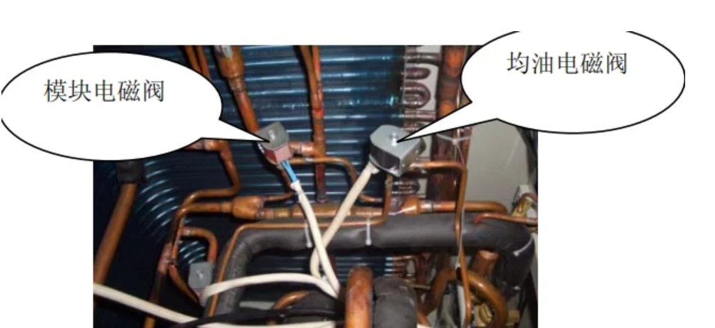
Outdoor units of multi-zone (VRF) systems contain several types of solenoid valves, each performing a distinct function in the refrigerant circuit, compressor cooling, or oil circuit. Misidentifying a valve during diagnosis leads to incorrect conclusions, so the following is a summary of seven common types with descriptions of operating principles, typical faults, and inspection recommendations.
Refrigerant Circuit Valves
Modular valve. Used in modular units with parallel connection of multiple outdoor units. Opens to connect a module to the refrigerant circuit and closes to isolate it when taken out of service.
- Does not open: flow capacity is limited, the compressor continues to run, suction pressure drops, discharge temperature rises — low-pressure or overheat protection trips.
- Does not close: refrigerant flows between running and stopped modules, disrupting refrigerant distribution and evaporation conditions.
- Diagnostics: do not rely solely on pressure readings; verify the control command, coil power supply, and pipe temperatures before and after the valve.
Liquid bypass valve. Part of the overheat protection circuit. Normally closed; when discharge temperature exceeds the threshold, it opens and feeds high-pressure liquid refrigerant into the low-side circuit, where it is throttled and absorbs heat, reducing the unit temperature.
- Does not open: cooling is not provided, discharge temperature remains elevated, overheat protection trips.
- Does not close: high-pressure refrigerant continuously flows into the low-side circuit, superheat of suction vapor decreases, and the risk of liquid slugging increases.
- The liquid bypass valve is not identical to the injection valve: the liquid bypass directs refrigerant into the low-side pipe, whereas the injection valve feeds liquid into a dedicated compressor cooling circuit. In some models the functions are combined — always verify the piping schematic before repair.
Hot gas bypass valve. Used to stabilize operation at low load and in cooling mode at low outdoor temperatures. Directs hot compressor discharge gas into the low-side circuit to regulate system pressure. Two typical scenarios: minimum indoor load (preventing frequent compressor start/stop cycles) and cooling at low outdoor temperatures (stabilizing low pressure and ensuring liquid flow through the expansion device).
- Does not open: unstable operation at low load, frequent start/stop cycles; in cooling at cold outdoor conditions, low-pressure anomalies may occur.
- Does not close: suction temperature rises, pressure ratio changes, cooling capacity decreases, and compressor load increases.
- Not all VRF systems are equipped with a dedicated hot gas bypass valve; a low-pressure anomaly does not necessarily indicate its failure — refer to the control logic of the specific unit.
Unloading valve. Designed to unload the compressor at startup or to regulate load in normal operation. A portion of high-pressure gas is diverted through a dedicated pipe, reducing load during startup and operation. The design varies significantly by model; it is not always a direct bypass from discharge to suction.
- Does not open: high starting load, large inrush current, difficult startup, overload protection trips.
- Does not close: hot discharge gas continuously flows into the suction circuit, suction temperature rises, compression efficiency and cooling capacity decrease.
- Diagnostics: always refer to the schematic and determine the actual function based on pipe connections.
Compressor Cooling
Injection valve (liquid cooling). A dedicated compressor cooling valve. When discharge temperature reaches a set threshold, it opens; liquid refrigerant from the condensation side is throttled and fed to a specific compressor cooling point, absorbing heat and preventing overheat. The injection point depends on the compressor design and does not always coincide with the compression chamber.
- Does not open: cooling does not function, discharge temperature remains elevated, protection trips.
- Does not close: refrigerant continuously flows into the compressor, abnormal superheat of suction vapor, increased risk of liquid slugging.
- Diagnostics: comprehensive assessment based on discharge temperature, injection pipe temperature, and coil actuation status.
Oil Circuit
Oil return valve. Works in conjunction with a capillary tube and filter for periodic oil return. Oil carried out of the compressor by refrigerant is returned to the outdoor unit, ensuring lubrication.
- Does not open: the oil return path is blocked; during prolonged operation the compressor runs with insufficient oil, accelerating wear. A clogged filter or capillary, or insufficient pressure differential for return, produce symptoms identical to a valve fault.
- Does not close: abnormal flow through the circuit, oil and refrigerant flow patterns are disrupted, and oil distribution becomes uneven.
- Diagnostics: simultaneously check the filter, capillary, oil circuit pressure differential, and oil level in the compressor.
Oil equalization valve. A dedicated oil circuit valve for modular VRF systems. Equalizes oil quantity between outdoor unit modules. Because module loads and operating times differ, oil levels shift; the valve, together with the pressure differential and control program, performs redistribution.
- Does not open: equalization does not occur, individual modules continuously run with insufficient oil, and wear increases.
- Does not close: oil continuously flows between modules, and oil levels in different modules diverge.
- This is an oil circuit valve, not a refrigerant circuit valve; diagnose based on oil level changes, equalization program logic, and oil path flow, not refrigerant pressure. Oil flow direction is determined by the pressure differential between modules and control logic.
Source: 制冷百科, 2026-11-05.
ORIGINAL SOURCE
制冷快报 ↗Visit the original source for additional details.