Components & controls
Reference Guide to Key Air Conditioning System Components: Operating Principles, Parameters, and Diagnostic Methods
This overview article examines the design and functions of 22 major components of climate control equipment — from compressors and electronic valves to controllers and power modules. For each element, operating parameters, integrity criteria, and basic testing procedures are provided. The material is intended for specialists learning to service and diagnose air conditioning systems.
An air conditioning system consists of dozens of interrelated components, each performing a specific function in the cooling or heating cycle. Below is a structured overview of 22 key components: their role in the circuit, key parameters, and basic testing methods. The material is aimed at specialists learning to service and diagnose climate control equipment.
Refrigerant Pumping and Reversal Cycle
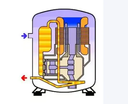
The compressor is the power element of the cycle: it draws low-pressure vapor from the evaporator, adiabatically compresses it to a high-temperature superheated state, and delivers it to the condenser, providing the pressure differential and refrigerant flow through the circuit.
A crankcase heater (25–61 W; for low-temperature applications — closer to the upper limit) is mounted beneath the compressor. During standby, it maintains the oil sump temperature to prevent refrigerant from dissolving in the oil; at startup, this prevents lubricant loss and liquid slugging.
The four-way reversing valve switches the circuit between cooling and heating modes and initiates defrost. It comprises a body, a sliding spool, and an electromagnetic coil: in cooling mode the coil is de-energized, in heating mode it is energized. The nominal coil resistance is 1,000–1,800 Ω; if the measured value deviates significantly, the valve should be replaced.
The electronic expansion valve (EEV) is a high-precision throttling element that provides dynamic regulation of refrigerant flow to the evaporator under varying load, particularly in inverter systems. To check integrity, winding resistance is measured: for a five-wire EEV, resistance from the common terminal to each phase is 47 Ω ± 3 Ω, between two phases — 94 Ω ± 3 Ω; for a six-wire EEV — within a group 47 Ω ± 3 Ω, between groups — infinity.
The gas-liquid separator is installed on the suction line between the evaporator and the compressor: it retains unevaporated liquid phase, preventing liquid slugging, while the lower drain channel returns oil to the compressor. This protection is especially critical in low-temperature operation and when heat exchange in the evaporator is insufficient.
The oil separator is mounted on the compressor discharge line. Hot vapor leaving the compressor carries oil particles; the oil separator captures them and returns them to the sump through the lower drain, preventing oil from accumulating on heat exchanger walls.
The receiver (accumulation tank) is located between the condenser and the EEV. It stores excess liquid phase, smooths out pressure pulsations, and further separates vapor from liquid, reducing the risk of moisture reaching the throttling device and valve icing.
The check valve is a passive element that allows refrigerant flow in one direction and blocks reverse flow. In heating mode, it prevents refrigerant from migrating to the side opposite the active circuit, maintaining pressure stability after shutdown.
High- and low-pressure service valves are installed at the inlet and outlet of the outdoor unit's refrigerant lines. They ensure airtightness and serve as points for vacuum pumping, charging, and repair; the connection is tapered. In normal operation, both valves must be fully open.
The filter-drier is connected in series between the condenser and the EEV: it traps mechanical contaminants and adsorbs residual moisture, protecting the throttling device from clogging and the circuit from corrosion. The internal cartridge may be mesh, paper, or powder (sintered) type; inspection frequency depends on operating conditions.
Sensors and Protective Automation
Pressure sensors are installed on the discharge and suction lines, converting refrigerant pressure into an electrical signal for the controller. During diagnostics, the zero-output voltage and linearity of response under applied pressure are checked; no response indicates a failed sensor.
Temperature sensors (NTC thermistors) — resistance decreases as temperature rises. A typical air conditioning system uses seven types:
- Discharge temperature sensor — compressor superheat monitoring;
- Compressor valve temperature sensor — monitoring of suction and discharge circuits;
- Indoor air temperature sensor — adjustment of compressor and fan speed;
- Outdoor unit defrost sensor — initiation and termination of the defrost cycle;
- Bulb sensor at the EEV outlet — valve position correction;
- Mid-point sensor in the indoor heat exchanger — protection against overcooling/overheating, linked to the fan;
- Outdoor temperature sensor — energy efficiency optimization.
Circuit pressure is limited by high- and low-pressure cutout relays: when the pressure exceeds the allowable range, the relay disconnects compressor power; after the cause is eliminated, a manual reset is required.
The phase-sequence relay is intended for three-phase non-inverter compressors. In case of incorrect phase sequence or a phase break, it instantly opens the power circuit. During installation and maintenance, phase correctness must be verified; relay functionality is confirmed by visual inspection, static measurement, and fault simulation.
The bypass solenoid valve connects the discharge line to the suction manifold. When pressure exceeds a set threshold, the valve opens, directing a portion of hot refrigerant to the low-pressure side, reducing discharge pressure and protecting the compressor from overload. It is used primarily at startup and in low-temperature heating mode.
The current detector measures the operating current of the compressor, fans, and other loads, provides overcurrent protection, and transmits the signal to the controller. In inverter air conditioners, non-contact Hall-effect sensors (open-loop or closed-loop) are typically used.
Power and Control Electronics
The main board (controller) is the control center: it receives signals from all sensors and communication data, generates control commands based on built-in logic, and displays status and fault codes on indicators, a digital display, or a wall-mounted remote.
The inverter module works in conjunction with the drive control board: high-power semiconductor switches with high switching frequency generate variable-frequency AC to power the compressor. The most integrated solution is the IPM (Intelligent Power Module), which combines the driver, overcurrent protection, overtemperature protection, and undervoltage protection.
In outdoor units of multi-zone systems, fans are typically permanent-magnet with variable-frequency drive: the fan drive board receives commands from the controller and smoothly adjusts speed to match the heat exchanger's thermal load. In single-zone (non-inverter) outdoor units, the fan is switched by a relay or contactor without a separate control board.
The power filter board performs bidirectional EMI filtering: it suppresses line-borne interference to protect electronic circuits and limits the emission of its own noise. It comprises inductors, high-voltage capacitors, and other passive components.
The main contactor is the primary power switch in the outdoor unit circuit of a multi-zone system. Controlled by a controller signal, it switches power to the compressor and outdoor fan (high currents). The four-way valve is typically actuated by a small relay and is not within the contactor's control zone.
The drain pump is used in floor-ceiling and cassette indoor units to lift condensate. Standard lift is 50–85 mm; for cassette models — up to 500 mm above the unit. The drain pipe slope must be at least 1/100; the filter mesh must be periodically cleaned of blockages.
Summary
Stable air conditioner operation depends on the coordinated functioning of all the components listed above. Knowledge of operating principles, typical parameters, and simple testing methods for each component forms the foundation of routine maintenance and fault-finding.
Source: Refrigeration Encyclopedia, 10.11.2026.
ORIGINAL SOURCE
制冷快报 ↗Visit the original source for additional details.