Chillers & heat pumps
Subcooling in a Refrigeration Circuit: Measurement Methodology and Deviation Diagnostics
Subcooling is the parameter a field engineer uses to assess whether sufficient liquid is reaching the metering device and whether vapor is forming in the liquid line. The article covers the calculation formula, typical ranges for air-cooled and water-cooled machines, and a list of causes that push the value out of spec.
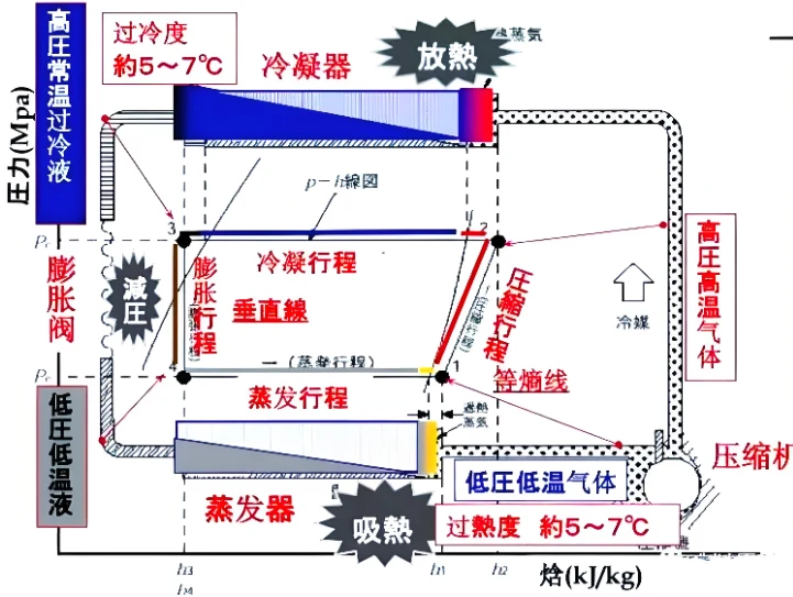
Subcooling is one of the key indicators used to judge the condition of a refrigeration circuit. Its primary function is to ensure that a sufficient volume of liquid refrigerant reaches the metering device and to prevent premature vapor formation in the liquid line, thereby stabilising the feed to the evaporator.
How to measure subcooling
The calculation is based on the difference between two quantities:
Subcooling = saturation temperature at condensing pressure − actual temperature of the liquid refrigerant
The saturation temperature is obtained by measuring the pressure on the high-pressure side and consulting the P–T chart for the specific refrigerant. The actual liquid-line temperature is read with a contact sensor at the condenser outlet.
Practical recommendations for measurements:
- The pressure measurement point should be located as close as possible to the condenser outlet; the temperature measurement point should be in the same cross-section to eliminate error from pressure drop and heat gain in the piping.
- The temperature sensor must be pressed firmly against a clean copper tube surface and insulated to reduce ambient influence.
- Infrared pyrometers are unsuitable for measuring copper tube temperature: the low emissivity of metal introduces a systematic error.
- For non-azeotropic mixtures (R410A and similar), the bubble-point temperature, not the dew point, must be used in the calculation.
Typical ranges
There is no single "normal" value — it depends on the machine type, refrigerant, condenser design, and operating mode. Approximate values for field assessment:
- Air-cooled chillers: 3–8 °C
- Water-cooled chillers: 3–8 °C
- Low-temperature units with an economiser: 8–15 °C (the exact value is determined by the economiser design and rated parameters)
These figures serve only as a first-order reference; the definitive criteria are set by the manufacturer's technical documentation and the design parameters. Subcooling is not a parameter where "higher is always better."
A moderate increase in subcooling raises the cooling capacity per unit mass of refrigerant, reduces the vapor fraction in the liquid line, and improves the circuit's efficiency. However, an abnormally high value may indicate liquid stagnation, incorrect charging, or an error in pressure or temperature measurement — in such cases a comprehensive analysis is required.
What deviations mean
Low subcooling indicates that the liquid refrigerant is close to its saturation temperature. If the pressure in the line drops further, vapor may form before the metering device, reducing its flow capacity and degrading heat transfer in the evaporator. Typical causes:
- Insufficient refrigerant charge: less liquid in the condenser, subcooling drops.
- Impaired heat transfer in the condenser: condensing pressure, saturation temperature, and line temperature shift.
- Elevated cooling-medium temperature: hot water on the inlet or high ambient air temperature at an air-cooled condenser.
- Excessive hydraulic resistance in the line: long piping, small diameter, clogged filter — pressure in the liquid line drops, increasing the risk of flashing.
High subcooling means the liquid at the condenser outlet is significantly colder than the saturation temperature. Possible causes:
- Overcharge of refrigerant: liquid accumulates in the condenser, the effective heat-transfer area shrinks, and condensing pressure rises.
- Favourable cooling conditions: low water temperature or good airflow cools the liquid further.
- Presence of a receiver: the refrigerant level in the receiver and the system operating mode affect the reading.
- Fault in condensing-pressure control: the regulator is malfunctioning and parameters drift out of range.
Important: high subcooling by itself does not prove elevated condensing pressure and does not automatically mean increased compressor power consumption. A correct conclusion requires correlating the high-side pressure, condensing temperature, liquid-line temperature, and compressor current.
Worked examples
Example 1. Air-cooled chiller on R22 (cold storage)
High-side pressure — 16 bar (gauge). From the P–T chart for R22, saturation temperature ≈ 44 °C. Contact sensor at the condenser outlet reads 35 °C.
Subcooling = 44 − 35 = 9 °C
The value is above the typical range for air-cooled machines (3–8 °C). However, this single reading is insufficient to conclude an overcharge. The receiver level, condensing pressure, line temperature, and actual refrigerant volume must all be checked. If elevated condensing pressure and rising compressor current are observed simultaneously, look for excess refrigerant or degraded heat rejection at the condenser.
Example 2. Water-cooled chiller on R410A (cold storage)
High-side pressure — 19 bar (gauge). From the P–T chart for R410A, bubble-point temperature ≈ 32 °C. Liquid-line temperature at the condenser outlet — 30 °C.
Subcooling = 32 − 30 = 2 °C
Subcooling is below the typical range. With a long line or significant pressure losses, the refrigerant may begin to flash before the metering device, disrupting stable feed. In this case, check the charge volume, condenser heat-transfer condition, cooling-water temperature and flow rate, and any abnormal pressure drop in the liquid line.
Source: Refrigeration Encyclopedia, 11.11.2026
ORIGINAL SOURCE
制冷快报 ↗Visit the original source for additional details.