Chillers & heat pumps
How to Interpret Chiller Parameters: Temperature and Pressure in Evaporation and Condensation Circuits
Correct diagnosis of a chiller's operating mode requires more than reading pressure gauge readings: saturated refrigerant temperatures must be cross-referenced with water inlet and outlet temperatures and pressure drops on the water side. The article covers key relationships, acceptable deviations, and the cooling-capacity calculation formula.
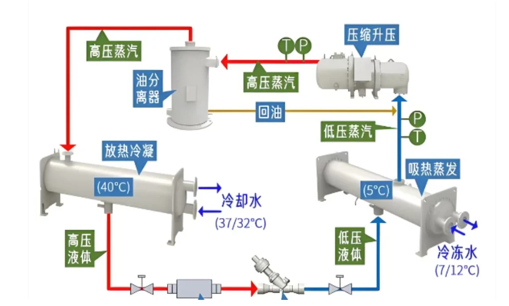
Accurate assessment of a chiller's operating mode requires more than simply reading high- and low-pressure gauge readings; it demands a comprehensive cross-reference of saturated refrigerant temperatures, water-side inlet and outlet temperatures, and pressure drops on the water side in both the evaporator and the condenser. These parameters directly determine cooling capacity, energy consumption, and operational stability of the machine.
Nominal Conditions and the Pressure–Temperature Relationship
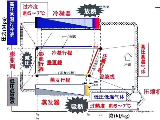
For a given refrigerant in a saturated state, evaporation pressure and boiling temperature are linked by a one-to-one relationship: an increase in pressure raises the saturated temperature, while a decrease lowers it. According to GB/T 18430.1–2024, the nominal operating mode for water-cooled chillers is defined as: chilled water 12 °C inlet / 7 °C outlet, cooling water 30 °C inlet / 35 °C outlet. These are performance calibration conditions, not a mandatory operating regime — the machine is not required to run continuously at these temperatures.
Evaporation Side
In normal operation, the refrigerant boiling temperature is 2–4 °C below the water outlet temperature from the evaporator. If the boiling temperature is too low, the compression ratio and compressor energy consumption increase, and there is a risk of evaporator frosting. If it is too high, the heat-exchange temperature differential drops and the cooling capacity fails to reach the required level. To assess whether the operating mode is normal, one must simultaneously consider the evaporator water outlet temperature, evaporation pressure, water flow rate, and actual load; relying on evaporation pressure alone is insufficient. As the load increases, the return chilled-water temperature rises, the thermal load on the evaporator grows, and both pressure and boiling temperature increase; when the load decreases, the parameters return to their previous values.
Condensation Side
The saturated temperature corresponding to the condensation pressure is the condensation temperature. In water-cooled chillers, the refrigerant rejects heat to the cooling water in the condenser; under normal conditions, the condensation temperature is 2–4 °C above the condenser water outlet temperature. This differential is determined by the condenser design, load, cooling-water flow rate, and the cleanliness of the heat-exchange surfaces.
All else being equal, an increase in condensation temperature raises the compression ratio and power consumption; a decrease reduces compressor work and improves energy efficiency. For centrifugal chillers, a rise in condensation pressure is particularly critical: it increases the likelihood of surge. When pressure rises abnormally, the first step should be to check heat exchange in the condenser and the cooling-water circuit.
Typical causes of elevated condensation pressure and temperature include: high cooling-water inlet temperature, insufficient flow rate, scale and fouling inside the condenser, and the ingress of non-condensable gases (e.g., air). When condensation pressure is abnormal, one should not immediately suspect a refrigerant leak — first, rule out issues with cooling-water temperature and flow rate and the state of heat exchange.
Water-Circuit Monitoring
For the chilled-water circuit, the key parameters are: inlet and outlet temperatures, the temperature differential between supply and return, and the pressure drop on the water side of the evaporator. The nominal temperature differential is 5 °C. At a stable cooling capacity, a higher flow rate produces a smaller differential, and a lower flow rate produces a larger one. Cooling capacity is calculated using the formula:
Q = 1.163 × G × ΔT
Example: at a cooling capacity of 1,000 kW and a 5 °C differential, the flow rate is approximately 172 m³/h. Insufficient flow degrades heat exchange in the evaporator and may trigger the minimum-flow protection; excessive flow increases pump energy consumption and hydraulic resistance on the water side. The pressure drop across the evaporator inlet and outlet reflects circuit resistance: a low differential may indicate insufficient flow, bypass flow, or a faulty sensor; a high differential may indicate filter or evaporator copper-tube fouling.
For the cooling-water circuit, inlet and outlet temperatures (nominal 30 °C / 35 °C, differential 5 °C) and the pressure drop on the water side of the condenser are monitored in the same manner. The heat rejected by the condenser includes not only the cooling capacity absorbed from the chilled water but also the heat released during compression in the compressor. At a constant heat load, a higher cooling-water flow rate produces a smaller temperature differential. A low pressure drop on the condenser water side typically indicates insufficient flow or a measurement fault; a high drop requires checking flow rate, filter, and condenser piping. Important: a high pressure drop does not mean better heat exchange.
Energy-Efficient Operation
Two practical principles: within the limits set by wet-bulb temperature, cooling-tower performance, and chiller parameters, aim to reduce the cooling-water inlet temperature; maintain a reasonable cooling-water flow rate that ensures adequate heat exchange without unjustified increases in pump frequency — otherwise, pump energy consumption rises sharply and overall system energy efficiency deteriorates. Optimization should account for the combined energy consumption of the chiller, pumps, and cooling towers, rather than pursuing solely the lowest temperature or the highest flow rate.
Source: 制冷百科 (Refrigeration Encyclopedia), 09.11.2026
ORIGINAL SOURCE
制冷快报 ↗Visit the original source for additional details.