Chillers & heat pumps
Three-Pipe VRF System with Heat Recovery: Architecture, Operating Modes, and Typical Faults
A three-pipe VRF system enables simultaneous cooling and heating of different zones in a single building through three main piping lines and a heat-recovery control unit (BS box). The article explains the function of each line, three operating modes, and five typical faults to watch for during maintenance.
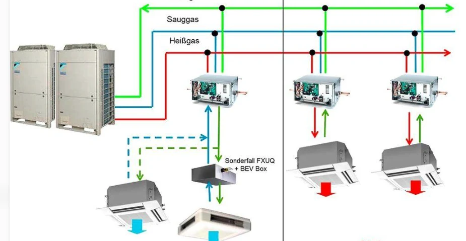
In large office and hotel buildings, it is common for some rooms to require cooling while others need heating. A conventional two-pipe VRF system cannot satisfy both demands simultaneously. A three-pipe system with heat recovery solves this problem by routing refrigerant through three main lines and a control unit (BS box) to the appropriate indoor units.
System Architecture
A three-pipe VRF system is a variable refrigerant flow (VRF) system with a heat-recovery function. Key components:
- High-pressure line (gas): delivers hot, high-pressure gaseous refrigerant from the compressor; in heating mode this line transfers heat into the rooms.
- Low-pressure line (gas): returns low-pressure gaseous refrigerant to the compressor after evaporation in the indoor units.
- Liquid line: delivers liquid refrigerant to the cooling zones.
- BS box (heat-recovery control unit): contains several solenoid valves and flow-control elements; switches refrigerant flow directions based on the demands of the indoor units.
Three Operating Modes
Cooling only. The compressor discharges hot gas into the outdoor heat exchanger, where the refrigerant condenses. After throttling, liquid refrigerant flows to the indoor units, evaporates, absorbs heat from the rooms, and returns to the compressor as low-pressure gas.
Heating only. Hot gas is routed through the BS box to the indoor units, where it condenses and releases heat to the room air. The condensate returns to the outdoor side, is throttled, evaporates in the outdoor heat exchanger, absorbs heat from the outside air, and enters the compressor. The indoor unit acts as a condenser; the outdoor unit acts as an evaporator.
Simultaneous cooling and heating (heat-recovery mode). Indoor units in cooling zones operate as evaporators; those in heating zones operate as condensers. The BS box directs refrigerant flow through the corresponding branches. A portion of the heat removed in the cooling zones is captured by the heating zones and is not rejected outdoors. When thermal and cooling loads are unbalanced, the outdoor unit continues to participate in heat exchange, compensating for any surplus or deficit of heat.
Difference from a Two-Pipe System
A two-pipe heat-pump VRF system does not allow different indoor units to operate in cooling and heating simultaneously. The three-pipe system, thanks to the BS box, provides this simultaneous mode, making it suitable for large buildings with a constant overlap of heating and cooling loads. The trade-off is a greater number of piping lines and control elements, a more complex design, and higher qualification requirements for installers, commissioning engineers, and service technicians.
Typical Faults and Diagnostics
In addition to standard issues with the compressor, electronic expansion valves, and sensors, a three-pipe system requires special attention to the BS box and its solenoid valves.
1. Reduced cooling capacity in individual indoor units. Possible causes: solenoid-valve failure on the cooling branch of the BS box, stuck valve spool and insufficient refrigerant flow, abnormal opening of the indoor unit's electronic expansion valve, clogging of the liquid line or filter. Method: compare operating parameters of a healthy and a faulty unit; check the EEV opening, pipe temperatures, and the condition of the corresponding BS-box branch; after confirming normal liquid supply, inspect throttling elements and pipe patency.
2. Reduced heating capacity in individual indoor units. Possible causes: failure to switch to the heating branch of the BS box, solenoid-valve fault on the high-pressure line, EEV or flow-control anomaly, refrigerant shortage, or degraded heat exchange in the indoor unit. Method: inspect the BS box serving the faulty unit, monitor the temperature of the high-pressure gas line and the liquid line, and compare with a healthy branch. If several units under the same BS box show a heating deviation, inspect the box itself and the shared piping first.
3. Inability to switch between cooling and heating modes. Possible causes: BS-box solenoid valve does not actuate, winding damage or power-supply fault, faulty BS-box control board, communication failure between the indoor unit and the box, system-level mode-switching restriction. Method: verify that the system received the mode-switch command, measure the voltage and resistance of the valve winding, and assess whether the valve actually actuated by observing temperature changes in the pipes. Important: a clicking sound from the valve does not guarantee that the spool is fully open.
4. Simultaneous failure of several indoor units under one BS box. Possible causes: faulty BS-box control board, multiple solenoid-valve failures, power or communication disruption, clogging of internal refrigerant channels in the box. Method: check power, communication, and the BS-box control board, then inspect valve windings and actual actuation. If several units under one box show the same fault while other zones operate normally, the priority is the box itself and its shared piping.
5. Reduced cooling and heating capacity of the entire system. Possible causes: refrigerant shortage or leak, fouled outdoor heat exchanger, pipe blockage, reduced compressor output, or load exceeding the actual capacity of the outdoor unit. Method: comprehensive assessment based on high- and low-side pressures, discharge temperature, compressor frequency and current, and outdoor heat-exchange conditions. Do not add refrigerant solely on the basis of a low low-side pressure.
Conclusion for Service Practice
When servicing a three-pipe VRF system, it is not enough to monitor the outdoor-unit pressure and compressor condition. One must understand the function of each of the three lines and the control logic of the BS box. When local deviations appear in individual units, it is essential to determine where the root cause lies: in the indoor unit, in a BS-box branch, or in shared system components.
ORIGINAL SOURCE
制冷快报 ↗Visit the original source for additional details.