Chillers & heat pumps
Chiller: Full Operating Cycle, Key Components, and Diagnostic Parameters
A practical guide to chillers: how heat is transferred through four main components, which three heat-exchange indicators are more sensitive than pressure, and what to check in each component during scheduled maintenance.
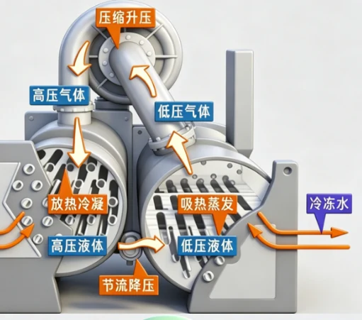
A chiller (refrigeration machine, refrigeration unit, ice-making unit) is the core of cooling in central air-conditioning systems and industrial cooling. It does not "produce cold": the refrigerant repeatedly changes phase in four main components, transferring heat from the chilled-water circuit to the cooling-water circuit, and then through the cooling tower to the atmosphere. According to the industry reference Refrigeration Encyclopedia (06.11.2026), most field failures are not caused by a single component failure but by a misunderstanding of circulation, hydraulic circuits, and operating modes.
Heat Transfer Cycle
By cooling method, chillers are divided into compression and absorption types; the compression type predominates in everyday operation. Four stages of the cycle:
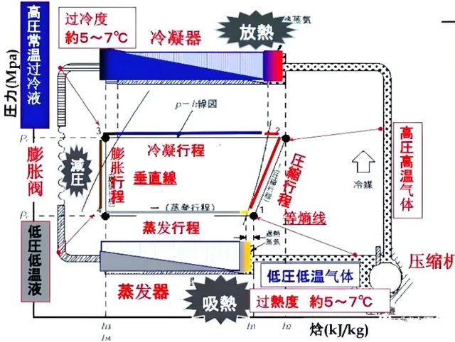
- Compression. The compressor draws low-temperature, low-pressure vapor from the evaporator and compresses it into high-temperature, high-pressure gas.
- Condensation. The hot gas enters the condenser, transfers heat to the cooling water, and condenses into high-pressure liquid. A built-in oil separator returns entrained oil to the compressor; the subcooling section further reduces the liquid temperature, increasing specific cooling capacity.
- Throttling. The high-pressure liquid passes through the expansion valve; pressure drops and a low-pressure, low-temperature two-phase mixture forms. The valve simultaneously regulates refrigerant flow to the evaporator based on the superheat signal.
- Evaporation. The two-phase refrigerant in the evaporator absorbs heat and evaporates, cooling the passing chilled water. Low-pressure vapor returns to the compressor, completing the cycle.
Two hydraulic circuits:
- Chilled-water circuit: water is cooled in the evaporator, pumped to fan coils, air distribution units, and other end users, absorbs heat from spaces, and returns to the evaporator.
- Cooling-water circuit: water is heated in the condenser, pumped to the cooling tower, cooled by contact with air, and returns to the condenser.
Four Main Components and Control Parameters
The compressor is the "heart" of the unit. In large machines, screw and centrifugal types predominate; in the commercial and small segment, scroll compressors are common. In-service checks: suction and discharge pressure, discharge temperature, operating current, oil level and temperature (normal ≈ 35–65 °C).
Condenser. Gaseous refrigerant enters from the top, passes through the built-in oil separator for oil-gas separation, then is cooled by cooling water on the heat-exchange tube surfaces and condenses. Main elements: built-in oil separator, shell, heat-exchange tubes (high-efficiency), tube sheets, support plates, subcooler.
Throttling device — the center of system regulation. Two functions: (1) reducing pressure from condensing to evaporating level; (2) dynamic adjustment of refrigerant flow based on superheat at the evaporator outlet — utilizing the full heat-exchange area without risk of liquid slugging or hydraulic hammer in the compressor. Common types: thermostatic expansion valve, electronic expansion valve, capillary tube, float valve.
Evaporator. Low-temperature, low-pressure refrigerant evaporates, absorbing heat and cooling the chilled water. Evaporation is a phase transition occurring at approximately constant pressure and temperature; in practice, the chilled-water temperature decreases.
Three Indicators More Sensitive Than Pressure
To assess heat-exchange quality, the reference highlights three parameters:
- Approach temperature at the evaporator/condenser (difference between outlet temperature and the corresponding saturation temperature) — typically should be less than 4 °C.
- Cooling-water temperature difference between inlet and outlet — approximately 5 °C.
- Cooling-water outlet temperature — typical upper limit ≈ 37 °C; exceeding it raises condensing pressure and reduces energy efficiency.
Auxiliary components of the unit include: sight glass, desiccant filter, oil separator, high- and low-pressure controllers, water flow sensor, pumps, and cooling tower.
Source: Refrigeration Encyclopedia, 06.11.2026.
ORIGINAL SOURCE
制冷快报 ↗Visit the original source for additional details.